Wind-Driven Surface Currents – The Death Knell for Conventional Oil Booms

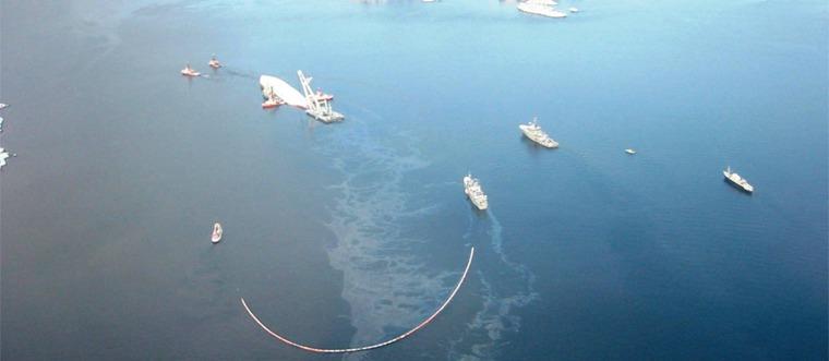
An oil boom is a device used to reduce the consequences of an oil spill on lakes or oceans by collecting, concentrating, guiding, encircling, stopping or absorbing oil floating on the surface.
To remove the oil contained by the oil boom, a pump or another type of mechanical device is used to bring the oil to a temporary storage unit, often a tank on an oil recovery vessel. Another option could be in-situ burning of the oil contained inside the oil boom.
Oil booms are normally divided into two categories: Conventional (classic, regular) oil booms and Active (tactical) oil booms. Conventional oil booms are normally manufactured in segments of 10-100 metres which can be connected together in infinite lengths. Active oil booms are often more compact systems, designed to operate in strong currents and/or at high towing speeds. These often have integrated special functions, for example oil storage and/or the ability to be towed by just one vessel.
CONVENTIONAL OIL BOOMS
A conventional oil boom consists of a freeboard (the buoyant element that keeps the system floating and creates a barrier above the surface) and a skirt, which is made of an impermeable material, often a coated fabric with weighted ballast that hangs down in the water. The freeboard often has a height of 200- 1400 mm and the skirt a depth of 300-2000 mm. The crosssection is approximately the same along the entire length of the boom. Some oil booms are made from oil-absorbent material and variants of these do not have a skirt, rather a freeboard of absorbent material that floats on the surface.
LIMITATIONS OF CONVENTIONAL OIL BOOMS
In the event of an oil spill, the oil will float on the surface when the specific gravity of the oil is less than the surrounding water. Oil booms creates a barrier, in which ‘clean’ water is on one side of the boom and surface-floating oil is on the other side. If the oil boom remains static, the light oil on the surface will naturally try to spread outwards.
When the oil boom is subjected to horizontal movement in relation to the water (by currents, towing of the boom or a combination of these) the oil thickness will gradually increase until it reaches a critical point, at which the oil escapes under the boom.
Three known fault mechanisms cause a loss of oil under the skirt: Drainage Failure, which is caused by local vortex currents and hydrodynamic suction, causing larger portions of the oil to escape under the skirt; Entrainment Failure, i.e. smaller oil droplets being dragged under the skirt, and the less recognized Critical Accumulation Failure. This occurs when the oil has a high viscosity and the oil slick is reduced to an infinitely short length when approaching the oil boom, and the entire slick passes under the skirt.
Drainage Failure and Entrainment occur at between approximately 0.5 to 0.9 knots (0.25-0.45 m/s), depending on the design of the oil boom, the shape of the boom being towed or anchored, and the type and amount of oil.
The failure type Critical Accumulation occurs at 0.3 knots* current for oil that has a viscosity of between 3 000 – 20 000 cSt. As a comparison, diesel, many crude oils, liquid honey and peanut butter have a viscosity of around 10, 100, 5 000 and 250 000 cSt respectively. In an oil spill, the oil’s viscosity will increase rapidly due to evaporation of the lighter fractions within the oil and the formation of emulsions (the water becomes mixed with the oil). For many crude oils the critical limit of 3000 cSt is often reached within hours after the spill.
*G.A.L. Delvigne, 1989, Barrier Failure by Critical Accumulation of Viscous Oil
The depth of the skirt, beyond a certain minimum depth, only marginally affects the ability to resist stronger currents; however, the skirt depth is important in relation to the amount of oil retained especially before the failure type Drainage Failure occurs. There have been reports of conventional oil boom designs involving specialized skirts optimised for minimal turbulence generation and maximal flexibility, especially in the lower part of the skirt, which under controlled conditions and with smaller amounts of lowviscosity oils have operated up to 1.2 knots before major loss of oil.
If the oil boom is deployed at an angle relative to the current, the ability to withstand current can be increased; however, this is difficult, as parts of the oil boom will often be perpendicular to the current and – not least – tidal currents (and possibly the wind) will change direction.
Several oil booms placed parallel to each other and spaced properly will also increase the ability to resist currents to some degree; however, by only a few 0.1 fractions of a knot.
There are other fault sources, such as mechanical failure, planing and splash over; however, these are not relevant for a correctly designed oil boom and are not relevant as a significant loss sources in the field. Freeboards over approximately 800 mm to 1000 mm contribute to boom efficiency to a very limited degree, as losses almost exclusively occur under the skirt.
OPERATIONAL ISSUES WITH THE USE OF CONVENTIONAL OIL BOOMS
Along the coast, there are many different currents to be taken into consideration when conventional oil booms are used.
Coastal currents are found along most coasts and these can be powerful – which in itself is sufficient to lead to the failure of conventional oil booms.
Tidal currents turn approximately every 6 hours and create a complex pattern of currents that can vary a great deal, even within a limited geographical area. They will also vary in intensity from day to day. For example, in narrow straits or where there are underwater reefs, the current can frequently rise to a speed of several knots. Even in open areas, the current can be considerable and above the critical oil boom speed.
The (often underestimated) wind-generated surface currents will generate a surface current of approximately 1.5 – 5% of the wind speed**, in which the weakest wind creates the highest current in %. In a moderate breeze of 5.5 m/s (12.3 mph), a surface current of 0.3 knots is generated, which in itself is at the limit at which an oil boom may fail. Even in a light breeze of 1.6 m/s (3.6 mph) a surface current of 0.16 knots will be created, which is strong enough to have to be taken into consideration in operational calculations.
**Haines, Bryson, An Empirical Study of Wind Factors in Lake Mendota
Internally, in non-breaking waves (swell) there is an orbital current or circular transport of liquids (particles) with a diameter approaching the height of the wave. Even moderate swell with height of a few metres may generate an orbital current of several knots. As this circular current has a limited depth, short time horizontal components, and the fact that the oil boom may be able to flex horizontally, the 0.3-0.9 knot failure limit cannot be applied directly. The mechanisms involved in this two-phase fluid wave scenario are highly complex and not fully understood; however, one thing that is certain is that the oil boom will fail in waves at a lower relative speed to water compared to calm water, due to the induction or promotion of hydrodynamic suction or vortex currents, leading to drainage failure.
In the case of wind-driven breaking waves, the front of the breaking wave will create a powerful local current in towards the oil boom, in addition to the wind-generated current. There has been no evidence that conventional oil booms have functioned effectively in wind-driven breaking waves, beyond smaller waves in harbours and similar areas.
In regard to the loss of oil, towing the oil boom will have the same effect as a current. Measuring the very low speed relative to water is a major challenge. Although a perception has developed that GPS alone is a completely ineffective tool for measuring the relative speed in relation to water, few vessels have good alternative instruments available. Even with good speed measuring devices it is extremely difficult – as the margins are so small – to tow an oil boom over time without at some point exceeding the lower critical limit. Note that sensors located deep on the hull will not be able to measure the wind-driven surface current correctly as there will be a current gradient down through the water column.
Attempts have been made to measure the speed through water and then fix the engine RPM in order to maintain an even speed. This is, however very difficult, as for example, a reduced distance between the vessels will lead to less resistance from the oil boom and thereby greater speed through the water. Another factor is that the wheelhouse of the vessel and the freeboard of the boom function as sails, and in a following wind this can be enough to exceed the critical limit. When the oil boom system passes a headland and hits a counter current, the mass of the towing vessel can briefly cause excessive speed.
The low towing speed may be less than the speed required for steering the vessel. The need to manoeuvre the towing vessel can mean that additional engine speed is required and the oil boom thereby exceeds the critical limit. Also, turning towing vessels, so that the propeller wash flows onto the oil booms, can easily lead to a boom exceeding the critical speed – and this in turn will lead to the instant loss of collected oil.
In order to collect oil from a blowout, attempts have been made to use speed measuring devices in the water (Doppler logs), which are mounted on the booms with an alarm installed at the bridge. This method has merit; however, the main problem is that when subjected to currents, vessels are forced to drift away from the blowout source in order to keep the boom speed below the oil loss limit. The oil slick will increase in width by in the range of 10 m per minute (depending on oil type and thickness), and as the oil boom system moves further from the oil spill site, the spread of the oil slick increases until the boom has limited effect, as most of the oil will pass along the side of the oil boom.

River estuaries discharging into the sea create complex local currents, as the lighter fresh water will spread out as it flows on top of the heavier seawater.
Local currents (rip currents) and backwash from waves that break on the shore can also create additional currents.
When conventional oil booms are deployed at sea, coastal currents, tidal currents, local currents from estuaries, propeller wash from vessels, orbital currents in waves, and towing may cause loss of collected oil – in addition to wind-driven currents. The sum of these current factors, along with the very narrow oil loss limits mean that in actual field conditions it is extremely difficult to operate a convention oil boom, except for in calm conditions without currents, wind and waves. There are grounds to pose the question whether the consequencereducing contribution planned for by using conventional oil booms, in many cases are significantly overrated.
ACTIVE OIL BOOMS
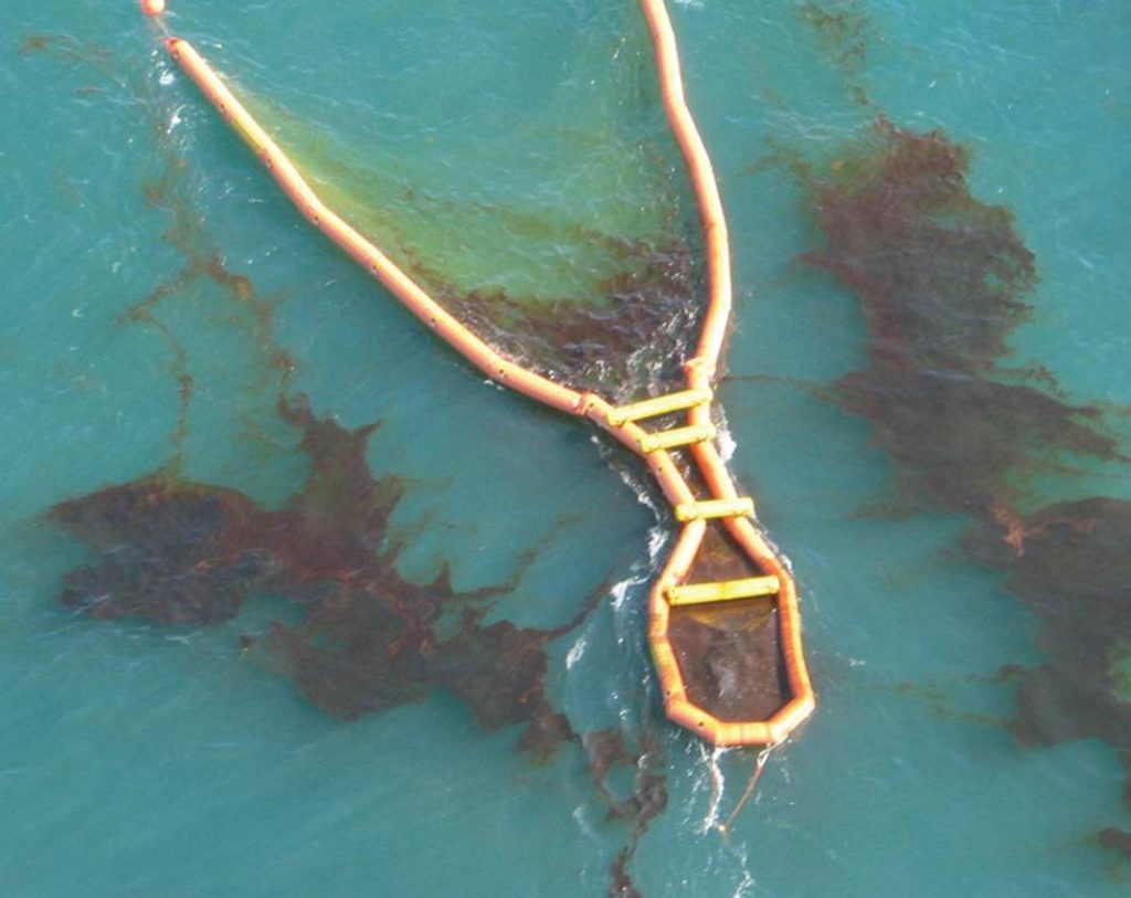
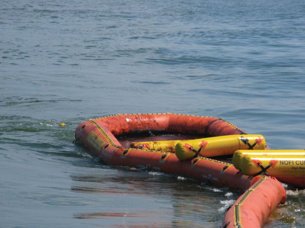
An active oil boom is constructed to collect and concentrate oil spills in more powerful currents than a conventional oil boom. The best active systems function effectively up to 5 knots through the water, regardless of the type of oil. Despite the fact that the technology has been applied for 15 years, it is only during the last few years that this type of boom has been in widespread use. The systems are often compact and may also be towed by a single-vessel. Active oil booms do not have the same appearance as regular long extended oil booms – in fact there have been discussions as to whether it is correct to call these oil ‘booms’ at all. Some of the systems are inflatable and can be stored compactly on a pallet or reel. Most systems have an internal storage tank for collected oil. In contrast to conventional oil booms, the oil in the storage tank is not lost if the system is operated beyond the current limits for a short time. Due to the higher towing speed, there are often physical limitations on the width of the front opening of between 10 – 50 m.
A good active oil boom will function at a speed through the water of 0-5 knots. The whole speed range is utilised to actively move through the water, moving from slick to slick, in order to collect as much oil as possible per time unit. The longer the distance between individual oil slicks, the greater the gains achieved from the high speed.
Some active oil booms have a minimum operating speed, i.e. they have to be towed at a certain speed, e.g. 1 knot before they can function; this can be somewhat challenging during, for example, passive shielding operations when there are no currents.
Active oil booms normally collect oil into a type of temporary storage device. There is a loss of oil involved in this process of 5- 25% depending on whether the booms are operated in waves, or not. However, this is a one-time loss, in contrast to a conventional oil boom that may lose oil continually unless the oil is pumped out.

Where conventional oil booms often do not function at all, the best active oil booms will, to a certain degree, (efficiency of 75 to 95%) function under most current conditions. However; there are exceptions, such as extreme tidal currents in local straits and rapid-flowing, extreme sections of rivers. Swell is not an issue; however, in wind-driven breaking waves there is some uncertainty in regard to the height of waves that active oil booms can withstand before the amount of one-time loss becomes unacceptable, the collected oil in the tank is lost from the systems or the extent that speed has to be reduced in breaking waves. In pure operational terms, there has been limited development of how active oil booms could be used in active shielding of, for example, fish farms or the formation of a barrier around a wrecked ship.
A conventional oil boom can actively (planned speed through water) be towed at maximum speed of around 0.1 – 0.5 knots if a, for example, 0.2-0.4 knot buffer, up to the fail limit of 0.3- 0.9 knots is used. The best active oil booms can readily be towed at a planned speed of over 4 knots, i.e. 8 – 40 times the towing speed of conventional booms. Despite the fact that the front opening is smaller than conventional oil booms and a one-time loss is involved when the oil enters the active boom’s storage tank, the efficiency will still be much greater.
Most important, the greatest contingency efficiency gains are, in any case, achieved in the predominant environmental conditions in which conventional oil booms do not function at all.
WHAT IS THE FUTURE OF CONVENTIONAL OIL BOOMS?
Oil spill responders have been aware of the limitations of conventional oil booms for quite some time, in relation to currents; however, the considerable and largely unpredictable contribution from wind-generated surface current has been less known, along with the very low 0.3 knot limit with respect to Critical Accumulation Failure.
Conventional oil booms are characterised by the fact that they work perfectly – within very narrow limitations. Unfortunately, actual field conditions are such that it is only in a limited number of scenarios that the parameters are within the range in which conventional oil booms function effectively. One of these exceptions may be first-line response close to a blowout, before the oil is broken up into smaller oblong slicks and before the viscosity exceeds the critical 3 000 cSt, if the aim of the operations is not to collect all of the oil, but as much oil as possible per time unit.
Thus far, conventional oil booms have been the primary tool used in most oil spill operations. There are grounds to query whether conventional oil booms should be downgraded to secondary tools that are planned to be deployed only in ideal conditions, and whether Active oil booms should take over the primary role in contingency plans. If so, responders will have a front-line field tool at their disposal that with a high degree of probability will function to an acceptable degree under most conditions, including wind-driven current.
Dag Nilsen, R&D Manager NOFI


